ZXmore or the ZX80CORE follow-up

Any discussions related to the creation of new hardware or software for the ZX80 or ZX81
User avatar
Lurch666
Posts: 36
Joined: Sun Nov 22, 2015 7:07 pm

Re: ZXmore or the ZX80CORE follow-up

Post by Lurch666 »

IORQ in green
A15 in yellow:

Image
User avatar
PokeMon
Posts: 2264
Joined: Sat Sep 17, 2011 6:48 pm

Re: ZXmore or the ZX80CORE follow-up

Post by PokeMon »

Hmm - this is strange and I have no idea now what happens here.
Could you just remove the following chips which might influence the data bus or address bus or give periodic signals:
IC3 (RAM)
IC16 (keyboard port)
IC22, IC24 (config latches)
IC14 (video latch)
IC11 (video counter)
IC13, IC18 (horizontal counters)

If the signal on A15 still no change then I think I would need the board on my table to check. Curious.
User avatar
Lurch666
Posts: 36
Joined: Sun Nov 22, 2015 7:07 pm

Re: ZXmore or the ZX80CORE follow-up

Post by Lurch666 »

Nope no change.
I can appreciate it must be difficult trying to diagnose a fault like this but thanks for trying.
P.M. me your address and I'll get it back to you.
User avatar
PokeMon
Posts: 2264
Joined: Sat Sep 17, 2011 6:48 pm

Re: ZXmore or the ZX80CORE follow-up

Post by PokeMon »

PokeMon wrote:
pablo9 wrote:So here's the whole screen. It's an old Dell 2001FP which I've used for ZXMORE in the past. Just looking at the photo again, it's interesting that the faint grey lines don't appear around all characters (eg. the numbers don't seem to have them, nor do the punctuation chars). It's not something to do with the changes for the upper/lowercase support?
Image

Coming back to this issue with the small lines between chars I am pretty sure this is an issue shown on full hd displays only. CRT should work well also displays with lower resolution. My plasma TV with 1024 horizontal pixels doesn't show this small grey line either. This is a timing mismatch between activating inverted chars which are used in the 128 chars charset (ASCII) to use the existing display routines. Chars upwards $40 are stored inverted and shown inverted which give the normal look. So all letters are involved. This is a delay of about 15-20ns which is about 10% of a ZX81 pixel or about 20% of a TV (CRT) pixel and this way not visible.

If you have 1920 Pixels in about 54us this is about 70-75% of a HD pixel so probably visible. I am not sure if there is an more or less easy workaround but I will think about it. So using a lower resolution TV shouldn't show up these small lines.
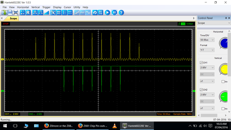
Coming back again to this issue - I had this today exactly when testing a new assembled ZXmore. I found out, that a new series of 74HCT165 Chips from Texas Instruments showed up a remarkable delay from loading data into the video shift register to the output of about 10-15ns more than an older TI chip. I tried this out with assembling the new chip into my first ZXmore and had the same effect and even on my broadcast monitor.

A workaround is to put a 47pF capacitor from pin1 of IC21 (74AC86) to GND (pin7 of IC21). This delays the invert signal to match with the video pixel data and removes these thin lines between the letters or at least make the picture better depending on your display. Didn't check out on HD TV but as this showed up on my CRT with higher resolution this could be somewhat fixed this way.
User avatar
PokeMon
Posts: 2264
Joined: Sat Sep 17, 2011 6:48 pm

Re: ZXmore or the ZX80CORE follow-up

Post by PokeMon »

Lurch666 wrote:Nope no change.
I can appreciate it must be difficult trying to diagnose a fault like this but thanks for trying.
P.M. me your address and I'll get it back to you.
Okay - one more working now.
I did find the problem quite fast while measuring around with the first test program and checking data lines at the RAM and found some suspicious signal on D4 (data line). This was quite different to D4 at ROM which could happen only if this signal is broken. By turning the board I found a missed solder joint. Too bad. But this is a very important solder joint (reading/writing data). I measured 1.4 MOhm to D4 of ROM.

I found 3 or 4 more at the 74HCT40103 which would just give a bad timing on the horizontal sync and unreadable picture but does not prevent the ZXmore from running in general.

After fixing both issues your board runs fine as far as I could test now. Unfortunately the keyboard is not present. But I did load a test program from USB which worked as well with wrapping some aluminium foil around my fingers. :mrgreen:
IMG_9065k.JPG
IMG_9065k.JPG (35.94 KiB) Viewed 3655 times
IMG_9067k.JPG
IMG_9067k.JPG (50.37 KiB) Viewed 3655 times
PS: I could not reproduce the problem with showing the signal in packets rather a continuous signal as discussed above. This may have been an issue with your digital scope only.
User avatar
Lurch666
Posts: 36
Joined: Sun Nov 22, 2015 7:07 pm

Re: ZXmore or the ZX80CORE follow-up

Post by Lurch666 »

I must have checked the board at least 10 times with a high power magnifying glass trying to see if I had missed anything-I must be blind.
Going to look at the photo I took of the underside to see if I can spot them.

EDIT:I see where I went wrong now.Those have a tiny bit of solder on the pad but it looks like I missed the legs so I saw the spot of solder and assumed they were done.

YEP-lame excuse but it's the best I've got. :oops:

thanks for sorting it out for me.As for not being able to reproduce the duff signals I think you might be right since I'm using a cheap oscilloscope.
Last edited by Lurch666 on Thu Apr 14, 2016 5:10 pm, edited 1 time in total.
Moggy
Posts: 3275
Joined: Wed Jun 18, 2008 2:00 pm

Re: ZXmore or the ZX80CORE follow-up

Post by Moggy »

Not only an excellent read but a great conclusion. :D
User avatar
1024MAK
Posts: 5123
Joined: Mon Sep 26, 2011 10:56 am
Location: Looking forward to summer in Somerset, UK...

Re: ZXmore or the ZX80CORE follow-up

Post by 1024MAK »

I have heard about people wearing tin foil hats, but...
PokeMon wrote:But I did load a test program from USB which worked as well with wrapping some aluminium foil around my fingers. :mrgreen:
So that's where we have been going wrong :lol:
I will try to remember, need tin foil hat and tin foil finger gloves :lol:

Good that the board has been fixed :D

Mark
ZX81 Variations
ZX81 Chip Pin-outs
ZX81 Video Transistor Buffer Amp

:!: Standby alert :!:
There are four lights!
Step up to red alert. Sir, are you absolutely sure? It does mean changing the bulb :!:
Looking forward to summer later in the year.
User avatar
Lurch666
Posts: 36
Joined: Sun Nov 22, 2015 7:07 pm

Re: ZXmore or the ZX80CORE follow-up

Post by Lurch666 »

So my ZXmore came back yesterday.
Spent half an hour putting the keys on (Easier than I thought) and spent the rest of the day (apart from 8 hours work) trying to find the damn battery that I took out before I posted it.Seems to work ok without it but annoyed I didn't put it somewhere safe.

Enjoying messing around with it and finding out what it can do.
Once I've got my 3D printer up and running again (fitting a new duel print head) I will print a nice ZX-80 case for this to live in.
User avatar
1024MAK
Posts: 5123
Joined: Mon Sep 26, 2011 10:56 am
Location: Looking forward to summer in Somerset, UK...

Re: ZXmore or the ZX80CORE follow-up

Post by 1024MAK »

The cell (battery) is only needed for the real time clock (RTC) which can maintain the current time and date. It's not used by ZX80 or ZX81 BASIC, or programs. It's mainly provided for future use with say C/PM.

Mark
ZX81 Variations
ZX81 Chip Pin-outs
ZX81 Video Transistor Buffer Amp

:!: Standby alert :!:
There are four lights!
Step up to red alert. Sir, are you absolutely sure? It does mean changing the bulb :!:
Looking forward to summer later in the year.
Post Reply