
Mark - your right. Found this online:
A low resistor value is called a strong pull-up (more current flows), a high resistor value is called a weak pull-up (less current flows).
Thanks - Tim
Time for some soldering (2x4.7k)
Has anyone been sucessfull interfacing ZXmore with ZXPand or ZXPand+ ?
Re: Has anyone been sucessfull interfacing ZXmore with ZXPand or ZXPand+ ?
Well. Bad news. Soldering 10k between 5vdc and A3 and removing the A3 jumper caused the same results. The ZXPand or ZXPand+ when plugged into ZXmore it displayed a screen with randomness hires graphics. I unsodered the 5v leg of the resistor and plugged back in the A3 jumper and powered back on the ZXmore to its normal screen again. Other ideas to look at?
Tim
Tim
- Attachments
-
- IMG_1264.JPG
- (5.85 MiB) Downloaded 313 times

Re: Has anyone been sucessfull interfacing ZXmore with ZXPand or ZXPand+ ?
I think this is only a wrong charset now, caused from the ZXmore firmware. It is necessary to do both, soldering this resistor 10k (can be steady, don't need to be removed) AND switching to a ZX81 instance directly with this switch. I think you still miss the switch. By default instance 0 is selected and this is different to instance 1 or ZX81 firmware as the char mappings are located somewhere else in flash memory. 
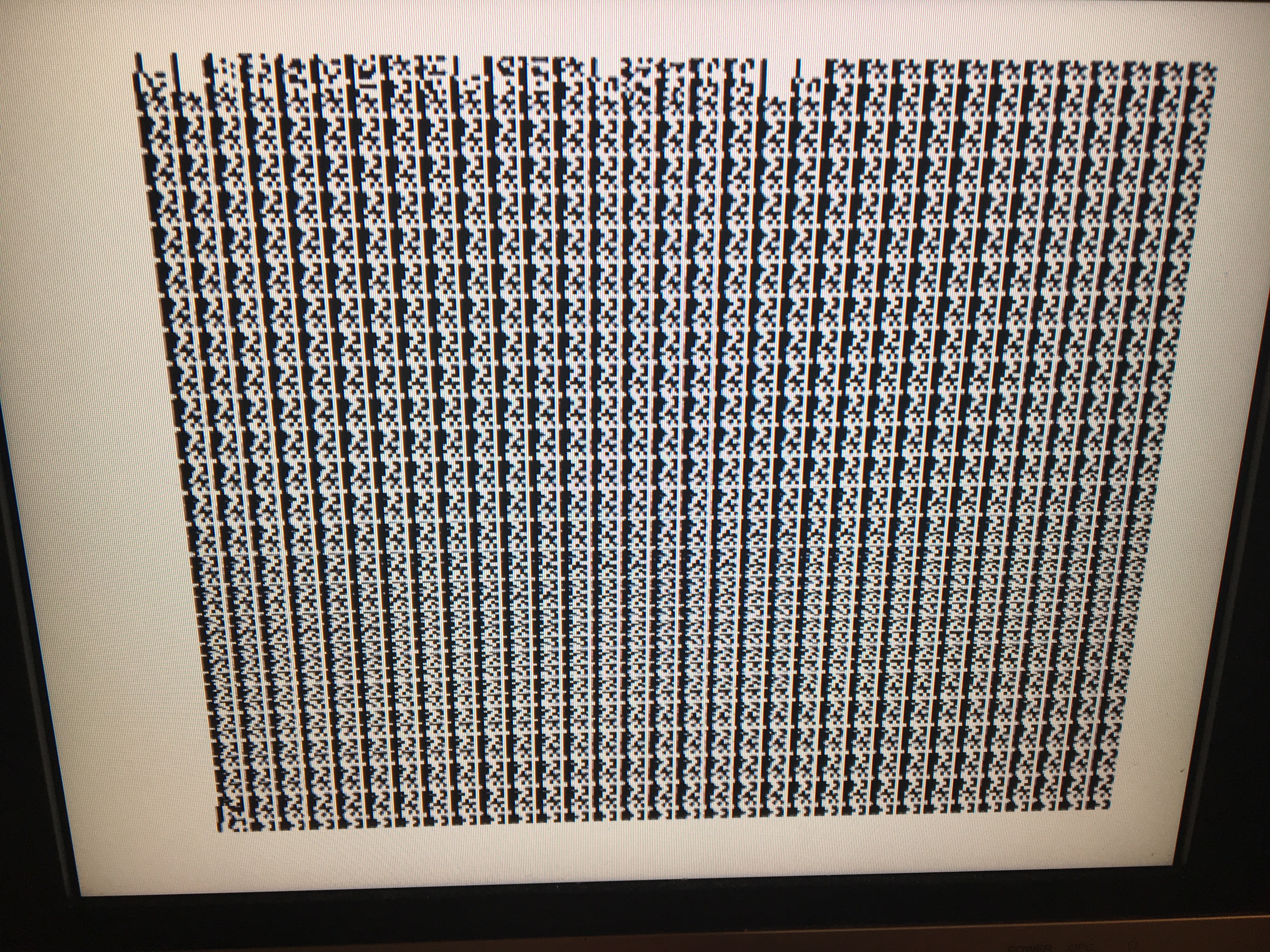
The picture shows just a different space char pattern, the cursor K below in last line (different pattern) and a kind of message in the first line (different patterns also). So the overlay ZXpand rom seems to be working in general. The (external) ROM overlay is only functional during code execution or data reading but not during displaying video data. This has technical reasons belonging to the ULA construction or replacement of this circuit with ZXmore internals.
The picture shows just a different space char pattern, the cursor K below in last line (different pattern) and a kind of message in the first line (different patterns also). So the overlay ZXpand rom seems to be working in general. The (external) ROM overlay is only functional during code execution or data reading but not during displaying video data. This has technical reasons belonging to the ULA construction or replacement of this circuit with ZXmore internals.
Re: Has anyone been sucessfull interfacing ZXmore with ZXPand or ZXPand+ ?
I soldered the 10k resistance back in with the A3 jumper in I get this with the ZXPand / ZXPand+ plugged in.
Whether the 10k resistance is soldered or not as long as the ZXPand / ZXPand+ is plugged in and A3 jumper removed I get the other picture from the last post showing the character pattern that Karl described
Whether the 10k resistance is soldered or not as long as the ZXPand / ZXPand+ is plugged in and A3 jumper removed I get the other picture from the last post showing the character pattern that Karl described
- Attachments
-
- IMG_1266.JPG
- (3.78 MiB) Downloaded 306 times
-
- IMG_1265.JPG
- (4.41 MiB) Downloaded 306 times
Re: Has anyone been sucessfull interfacing ZXmore with ZXPand or ZXPand+ ?
The trick is:
You can either use ZXpand set and A3 jumper removed and rotate switch set to 1
- or -
A3 set and ZXpand removed and rotary switch set to 0
It does not work with A3 jumper set and ZXpand attached due to an io address conflict as stated more above.
If you get this picture you are only a micron far from operation (just need to switch to position 1 if you have that switch)
Re: Has anyone been sucessfull interfacing ZXmore with ZXPand or ZXPand+ ?
Karl,
Since the rotary switch did not come with the v2 board, I will need to purchase one. I know with customs and shipping from Europe this has been costly and longer shipping time. Can you send me the specification on the switch and I'll see if I can find it in the USA through Amazon or Mouser or some other electronics online store.
Thanks,
Tim
Re: Has anyone been sucessfull interfacing ZXmore with ZXPand or ZXPand+ ?
It is named in the construction manual:
http://bit.ly/2tfYZtq
1 x KDR16H J17 (ROM switch, hex coded switch, right-angled, manufacturer OTAX)
It is a japanese manufacturer and not hard to get in Germany, have different sources.
See here for data sheet: The right angled type is also called KDR162H, the KDR162 may be good also.
You may also take KMR162(H) or KW162(H) with a knob integrated.
The KDR102(H) or similar would do as well, offering only 10 positions instead of 16 while 8 are sufficient (the other 8 or repeated from the first).
I have some spare here I can sell for EUR 2.00 plus shipment EUR 3.70 - so all in all EUR 5.70 and there won't be any customs for this small kind of item. Shipment indeed could take a small while, 7-10 days maybe from Europe. On the other hand I don't know any USA based source (distributor) and price for a single switch maybe more expensive as well including shipment. But up to you ...
And by the way - you could just connect pin 2 (A16) of the ROM (flash SST39SF040) with GND to have it fixed to instance 1 (ZX81). Could do this by a simple wire or place a different switch in this wire. This way you could at least test if it does what you want.
Re: Has anyone been sucessfull interfacing ZXmore with ZXPand or ZXPand+ ?
I soldered a 30 gauge wire between pin 2 (A16) and Pin 16 (Vss - assuming this is ground). The 10k resistance was still soldered between A3 and 5vdc and A3 jumper was out. However, it did not work and I got a similar sync looking offset screen.
Re: Has anyone been sucessfull interfacing ZXmore with ZXPand or ZXPand+ ?
What do you get in this configuration if you just remove ZXpand ?
Re: Has anyone been sucessfull interfacing ZXmore with ZXPand or ZXPand+ ?
It seems there is a small bug when clock frequency is set steady to 3.25 MHz (instead of toggling between 6.5 and 3.25).
Okay - was a kind of reset condition and fixed it with a CPLD change. There is a clock switcher in the CPLD which could not be initially set to low clock frequency and needed to first switch one time to high clock frequency and after changes automatically as desired (manual settings or video display active). So anyway you need a new CPLD now.
Had the 4 quadrant picture same as you in your picture, now works with normal display (ZX81 instance). Indeed you could type something in and due to double frequency you have four identical pictures (left, right, top and down). Doesn't look too bad but hard to read ...
I wonder how did you get the picture with the stable screen pattern - but maybe it is just a startup condition which appears or not after power-up randomly.
Last edited by PokeMon on Fri Aug 11, 2017 2:55 pm, edited 3 times in total.