Page 2 of 3
Re: Bodged 16K RAM upgrade in issue one
Posted: Fri Sep 08, 2017 3:16 pm
by Lardo Boffin
1024MAK wrote: ↑Fri Sep 08, 2017 1:10 pm
Lardo Boffin wrote: ↑Fri Sep 08, 2017 11:53 am
(There is a break between pin 6 and the track to its left - I removed a bit of green solder mask to double check)
Can you confirm with a meter, because it does not look cut in your photo. Oh and it's not pin 6...
Here is the bottom side track cuts from my guide:
ZX81 issue 1 - 04 - bottom of PCB after tracks cut 560.jpg
Mark
I think it was the wire on top of the pin making it look uncut. Regardless I have cut it some more and continuity tested it against the track to the left of pin 23(?).
Better image below
Re: Bodged 16K RAM upgrade in issue one
Posted: Fri Sep 08, 2017 3:17 pm
by Lardo Boffin
sirmorris wrote: ↑Fri Sep 08, 2017 2:50 pm
There's this:
Capture.PNG
Thanks - I think that is just from the printing of the number. There doesn't appear to be a physical break in the track.
Re: Bodged 16K RAM upgrade in issue one
Posted: Fri Sep 08, 2017 3:27 pm
by 1024MAK
BTW, did this board work before you started the modification?
Mark
Re: Bodged 16K RAM upgrade in issue one
Posted: Fri Sep 08, 2017 3:47 pm
by Lardo Boffin
1024MAK wrote: ↑Fri Sep 08, 2017 1:47 pm
Other possible problems:
Is it possible that a plated-through hole linking the tracks from one side of the board to the other came out when you removed the two SRAM chips?
Is it possible that there is a solder splash under the new socket?
You can test for breaks by testing that each "node" (connection point) connects to the other "nodes" for each track (meter on continuity range) - cross reference to the schematic. If you use a copy, you can mark off each in turn.
Mark
Going to be a busy night!
Through hole - I'm pretty sure I only damaged one. To repair it I basically pushed the end of the wire through the hole and seated it in the hole with the pin. I then soldered the socket from below so both sides should be connected on pin 7 of IC4. For the Z80 end I did similar and so get continuity from pin 7 of RAM to pin 35 of the Z80.
It has just occurred to me as I write this that I damaged the pad on IC4a (inside of 4) and therefore although I have connected pin 7 of IC4 to the Z80 did it connect anywhere else going via pin ## (4 possibly) of the IC4a socket?
I have just popped the RAM out and can see that the track pulled up on the other side as well. Not sure how I missed that!
If you zoom you can see that part of the letter C is missing from IC4a. Doh!
So (assuming I have got the pins right...) pin 7 of IC4 is not connected at all to pin 4 of IC4a so it is not carrying signals on either side of the board.
Time to remove the socket and tidy up the mess!
Re: Bodged 16K RAM upgrade in issue one
Posted: Fri Sep 08, 2017 3:48 pm
by Lardo Boffin
1024MAK wrote: ↑Fri Sep 08, 2017 3:27 pm
BTW, did this board work before you started the modification?
Mark
Yes it worked fine.
Re: Bodged 16K RAM upgrade in issue one
Posted: Fri Sep 08, 2017 11:25 pm
by Lardo Boffin
I used the snipped off leg of a capacitor (they also make great jumpers) to re-establish the broken link from IC4a pin 4 to IC4 pin 7 but still nothing.
I am going to leave for now for fear of making it worse!
Re: Bodged 16K RAM upgrade in issue one
Posted: Fri Sep 15, 2017 10:56 pm
by Lardo Boffin
So I have had a bit of time to prod it with a multi-meter and after a lot of tedious checking I eventually found that I had an unwanted connection as shown below: -
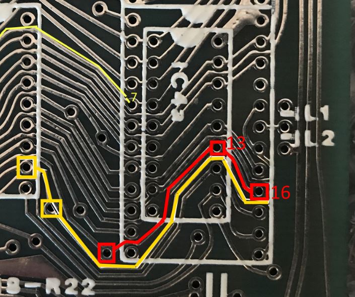
- Doh!.JPG (113.65 KiB) Viewed 3841 times
Pin 11 of IC4b had continuity with pin 16 of IC4 which it should not have. Yes at this stage I was testing literally every possible pin on all the sockets anywhere near...
Time to investigate the actual board as the two tracks were very close together in a few places. And I find a tiny blob of stray solder.

Very luckily inside the IC4a area so I don't have to remove the socket! Bonus. After a little careful scraping...
Re: Bodged 16K RAM upgrade in issue one
Posted: Fri Sep 15, 2017 10:59 pm
by Lardo Boffin
It's alive!!!!
Ok so the photo is a bit rubbish but you can see a K!
Lesson learned. Don't do this kind of thing when tired. Sadly this is all the time at the moment...

Re: Bodged 16K RAM upgrade in issue one
Posted: Sat Sep 16, 2017 5:28 am
by gammaray
Actually some of the rest of us learn something when other people find difficulty. Now your a teacher!

Thank you.
Re: Bodged 16K RAM upgrade in issue one
Posted: Sat Sep 16, 2017 9:11 am
by 1024MAK
Lardo Boffin wrote: ↑Fri Sep 15, 2017 10:56 pmAnd I find a tiny blob of stray solder.
Very luckily inside the IC4a area so I don't have to remove the socket! Bonus. After a little careful scraping...
Alas, these kind of faults are VERY tricky to find. So well done Phil (Lardo) on finding it. After I suggest looking for short circuits using a meter, some do a bit and then give up. It's amazing how a tiny solder splash can cause such as fault.
I'm not sure it was just tiredness. Sometimes things happen just because they can. On modern PCBs, a solder resist layer is used on each copper layer, and is really good at reducing accidental shorts caused by solder splashes. But the top (component) sides of ZX81 and ZX Spectrum computers don't have a solder resist layer so the risk of a short is much greater. And a tiny bit of silver coloured solder in amongst lots of bright silver colour PCB tracks, is hard to spot.
Anyway, Phil, put that down to experience, it may have been hard fought, but it's still a win
 Mark
Mark