Page 1 of 8
MIC amplifier
Posted: Mon May 02, 2016 10:24 pm
by mrtinb
I'm having trouble reading the MIC-signal to save from my ZX81.
I found a schematic in an old electronics book on how to amplify a signal with a transistor. Maybe I could make a little PCB with two mini jacks and this little circuit to better save my signal.
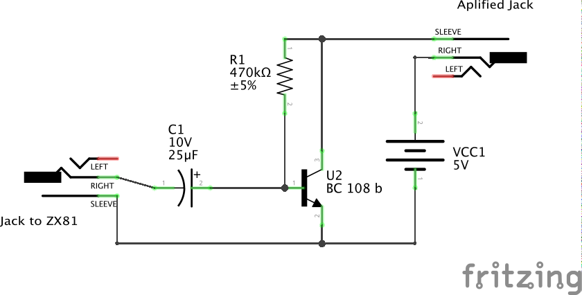
- zx81-amp_schem.png (35.9 KiB) Viewed 4222 times
Re: MIC amplifier
Posted: Mon May 02, 2016 11:54 pm
by 1024MAK
Um, how does the +5V get to the transistors collector load resistor? Speaking of which, where is the collector load resistor?
I would expect the +5V to go to the collector load resistor, then the other end of this resistor to go to the transistor collector terminal / junction with the base bias resistor (R1).
Also, a BC547/BC548/BC549 (even better with a B or C suffix) are cheaper and do the same thing (these are plastic cased versions of the BC107/BC108/BC109, the gain group is indicated by the letter suffix, C is higher than B, which is higher than A, no suffix letter means ungraded).
You should also include a capacitor in series with the output. The input capacitor (C1) can be a lot lower in value, say 1uF. The output capacitor can be say 10uF. But these are just guesstimates.
Also, I recommend you breadboard it first, so that you can change things if it does not work as expected. Then you can solder one together on strip board or matrix board or whatever.
Mark
Re: MIC amplifier
Posted: Tue May 03, 2016 12:04 am
by 1024MAK
Have a look at
this site. The resistor and capacitor between the emitter and the 0V/GND/ground give more control of the DC gain and provide a bit of negative feedback so that the bias of the transistor is more stable.
Mark
Re: MIC amplifier
Posted: Tue May 03, 2016 5:46 am
by mrtinb
1024MAK wrote:Um, how does the +5V get to the transistors collector load resistor? Speaking of which, where is the collector load resistor?
I would expect the +5V to go to the collector load resistor, then the other end of this resistor to go to the transistor collector terminal / junction with the base bias resistor (R1).
Maybe I've misinterpreted the experiment in this old beginners electronics book.
Re: MIC amplifier
Posted: Tue May 03, 2016 8:48 am
by 1024MAK
Ahh! That circuit is directly driving the ear-piece (earphone). The ear-piece is the load, hence no collector load resistor or output capacitor needed.
Mark
Re: MIC amplifier
Posted: Tue May 03, 2016 10:22 am
by mrtinb
I was thinking about building this little circuit between ZX81 and iPhone, because the signal is too low for the iPhone to record.
I'm not sure about the components' values. And I should probably find a newer cheaper plastic version of the capacitor (which did not exist at the time the diagram was made).
Re: MIC amplifier
Posted: Tue May 03, 2016 11:35 am
by mrtinb
I assumed a earphone could be replaced by a mini jack. It might not be so.
Re: MIC amplifier
Posted: Wed May 04, 2016 2:17 pm
by Moggy
When ever I want to bring a small audio signal up to line level I make something like this,but replacing the 741 shown with something like an NE5534 which is less noisy and has a bit more punch.
Thought to honest such pre-amps are now so inexpensive to buy ready made it's not worth building yourself.
Re: MIC amplifier
Posted: Wed May 04, 2016 10:56 pm
by mrtinb
Moggy wrote:Thought to honest such pre-amps are now so inexpensive to buy ready made it's not worth building yourself.
Like this one?
TDA1308 Headphones amplifier board For the Power amplifier Pre-amp amplification use
Re: MIC amplifier
Posted: Thu May 05, 2016 2:19 am
by XavSnap
HI,
Juste add two 5v. LEDs, it will protect your iPhone against voltage overloads and product a 5v. scare signal.
On this diagram, it's the Ear signal... but, it the same method on the output signal.
