Page 3 of 8
Re: MIC amplifier
Posted: Wed May 18, 2016 9:18 am
by PokeMon
I think mrtinb is more looking for a solution working with original hardware without inside modifications.

Re: MIC amplifier
Posted: Wed May 18, 2016 9:37 am
by mrtinb
PokeMon wrote:I think mrtinb is more looking for a solution working with original hardware without inside modifications.
Yup

Re: MIC amplifier
Posted: Thu May 19, 2016 6:19 pm
by mrtinb
mahjongg wrote:you can try implementing the mic pre-amplifier I've built into my ZX81 clone, which is working well.

If I try to input it into this simulator, the output is not much (240mV). Maybe I've set up the simulation wrong.
http://www.falstad.com/circuit/circuitj ... .6+1+-1%0A
Re: MIC amplifier
Posted: Sat May 21, 2016 9:28 pm
by mahjongg
Martin, the main setup problem was that 5mV is far too low a signal level, a cassette player (or laptop) would put out at least a few hundred mV, upto few volt peak/peak or so. Also you set the "Time step size" too high, so the "scope" signal becomes too dense to see anything.
I tweaked the settings a bit, and now it works well:
http://www.falstad.com/circuit/circuitj ... 25+1+-1%0A
it uses a 300mV cassette level, and turns it into a TTL compatible (5V) signal, that is what it was designed to do.
nice online app by the way, I still prefer the more serious simulators though, in this case LTSPICE specifically because you have more flexible input signal generators that can imitate the ZX81 cassette signal, including the signal intervals.
Re: MIC amplifier
Posted: Sun May 29, 2016 9:40 pm
by mrtinb
Hi
Now I’ve set up the pre-amp on a little breadboard.
It doesn’t amplify the MIC signal, so I try to debug what is wrong.
But when I measure the signal from MIC on the ZX81, I get 0.0V when nothing is saving. And 0.0V when I save a program.
I have set my multimeter on 200 mV.
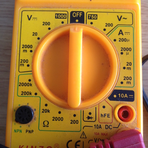
- IMG_2802.JPG (120.26 KiB) Viewed 3062 times
Re: MIC amplifier
Posted: Mon May 30, 2016 1:18 am
by mahjongg
I actually wrote quite a lot about getting my pre-amp to work as it should, perhaps you could read it to find out why your version is not working.
at least during periods of no signal the output should indeed go low. my first failed attempt indeed failed to do so, and was high (5V) in the pauses, resulting in a permanent black screen
https://revspace.nl/ZX81%2B34_ZX81_clon ... rt_working
Re: MIC amplifier
Posted: Mon May 30, 2016 2:21 am
by PokeMon
You can't measure this with a multimeter.
Normally you could expect 4-5mV pulses, which give an equal of about 2mV and when calculating the pause of 1300us between pulse packages it should be more between 0-1mV (average).
Re: MIC amplifier
Posted: Mon May 30, 2016 6:12 am
by mrtinb
PokeMon wrote:You can't measure this with a multimeter.
Normally you could expect 4-5mV pulses, which give an equal of about 2mV and when calculating the pause of 1300us between pulse packages it should be more between 0-1mV (average).
Can I see the signal with a digital probe?
Re: MIC amplifier
Posted: Mon May 30, 2016 9:50 am
by 1024MAK
Don't forget, the signal you are trying to measures is an audio AC signal. So you need a sensitive multimeter that has a mV AC range AND which is rated to correctly measure audio frequencies. The cheaper meters are only designed to measure 50Hz to 100Hz on their AC ranges, which is no good for this application.
A digital probe will also be no good.
The best test gear for working on audio amplifiers and signal tracing is an oscilloscope. However, there is now some suitable application software that will run on a PC if you have a decent sound card, and which can be used to display audio waveforms.
But no having used any of these, I have no idea if they will pick up very low 2 to 5mV signals.
If you provide all the DC bias voltages at each junction (show on a copy of a schematic), that may give a clue as to what is wrong. So for example, as a minimum, at the base, collector and emitter of the transistor(s).
Mark
Re: MIC amplifier
Posted: Mon May 30, 2016 11:13 am
by mrtinb
The problem is that the signal is too low for the PC to see, that's why this pre-amp is made.
Maybe I could connect it to my audio mixer, and debug through the circuit by listening to the output.