
MIC amplifier

Re: MIC amplifier
You can connect it to your PC and listen if you can hear something using the mic port in PC.
-
1024MAK

- Posts: 5118
- Joined: Mon Sep 26, 2011 10:56 am
- Location: Looking forward to summer in Somerset, UK...
Re: MIC amplifier
So I take it this is the schematic of the circuit you are using:
Are you using a mono 3.5mm jack plug for the connection to the ZX81? A stereo (two channel) jack plug is no good, as the contacts do not line up correctly in the socket.
Can you measure the DC voltages at the points indicated with no input signal present please. Report back the results.
The idea of using the oscilloscope application on the PC is to see if it can see a waveform at the output.
Mark
- Amplify the tape output signal from a ZX81
- Amplify the tape output signal from a ZX81.png (12.04 KiB) Viewed 3720 times
Can you measure the DC voltages at the points indicated with no input signal present please. Report back the results.
The idea of using the oscilloscope application on the PC is to see if it can see a waveform at the output.
Mark
ZX81 Variations
ZX81 Chip Pin-outs
ZX81 Video Transistor Buffer Amp
 Standby alert
There are four lights!
Step up to red alert. Sir, are you absolutely sure? It does mean changing the bulb
Looking forward to summer later in the year.
ZX81 Chip Pin-outs
ZX81 Video Transistor Buffer Amp
There are four lights!
Step up to red alert. Sir, are you absolutely sure? It does mean changing the bulb
Looking forward to summer later in the year.

Re: MIC amplifier
I don't have a MIC input on my Mac, but I think I'll buy Oscilloscope for iOS app for my iPad, and use my audio mixer to amplify when the input is too low.1024MAK wrote:The idea of using the oscilloscope application on the PC is to see if it can see a waveform at the output.

Re: MIC amplifier
you should see something like this:
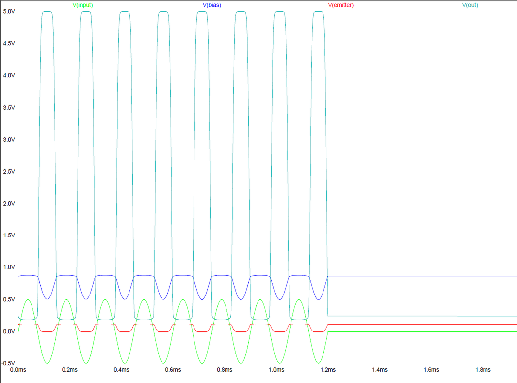
Green is the audio input signal (1 volt peak/peak in this case, but the amp will accept smaller signals)
Blue is the signal on the transistors base, dipping below the nominal 0.8 Volt on the negative phase of the input signal
Red is the voltage on the emitter, and is the same as the emitter current
cyan (light blue) is the output signal, going fully from logic low to 5V.
my amplifier was designed to convert an audio input level (line-level) signal to a HC logic compatible digital signal to input into a 74HCxx device.
Re: MIC amplifier
Before 82K: Before 220R: After 10K: It most likely doesn't work, because I used components I had at hand, which were slightly off the values.1024MAK wrote: Can you measure the DC voltages at the points indicated with no input signal present please. Report back the results.
- 47pF exchanged for 4.7pF
- 4.7nF exchanged for 0.1uF
- BC847B exchanged for PN2222A
Getting this oscilloscope app makes it quite easier to debug, and it was only €4.99, and a TRRS mini jack for the connection to the iPad.
Re: MIC amplifier
strange. even with these different values the pre-amp should work, the resistor values are the most important factor, they should steer the transistor just enough open to drive the output (collector) low. a small negative signal through the 47nf (100nF) capacitor should be enough to drive the base below the threshold where the transistor starts to conduct.
Re: MIC amplifier
Thank you mahjongg, for correcting this simulation to output between 0V and 5V.mahjongg wrote:Martin, the main setup problem was that 5mV is far too low a signal level, a cassette player (or laptop) would put out at least a few hundred mV, upto few volt peak/peak or so. Also you set the "Time step size" too high, so the "scope" signal becomes too dense to see anything.
I tweaked the settings a bit, and now it works well:
Falstad Circuit Simulator - ZX81 pre-amp
it uses a 300mV cassette level, and turns it into a TTL compatible (5V) signal, that is what it was designed to do.
nice online app by the way, I still prefer the more serious simulators though, in this case LTSPICE specifically because you have more flexible input signal generators that can imitate the ZX81 cassette signal, including the signal intervals.
- Shouldn't the output be between 0V and 2V for line level recording?
- The simulation's input is 300mV. Unfortunately when I measure my ZX81 MIC output the signal is 10mV.
- Can I change the values of the components so the output is between 0V and 2V, when the input is 10mV?
- Or do I need an extra transistor to amplify to signal twice?
Re: MIC amplifier
No the output is 5V, because its fed into a 5V logic device that needs 5V logic, this is not simply a preamplifier its a circuit designed to take audio levels from the sound played from a laptop, and convert them so that they will become ideal Transistor Transistor logic levels inside the ZX81.
- Shouldn't the output be between 0V and 2V for line level recording?
- The simulation's input is 300mV. Unfortunately when I measure my ZX81 MIC output the signal is 10mV.
- Can I change the values of the components so the output is between 0V and 2V, when the input is 10mV?
- Or do I need an extra transistor to amplify to signal twice?
No 300mV is the kind of level coming out of a laptops sound card when playing off ZX81 recordings, it the level the circuit was designed to handle 10mV is far too small, about 20 times too small.
No, You Cant, you could use a pullup to 2 Volt instead of 5Volt, but it won't improve sensitivity, its NOT a microphone pre-amp.
you might, but why bother with my circuit then? just feed the 50 times amplified signal directly to a ZX81, My circuit is simply an improved input circuit that accepts signal levels somewhat lower than than inputting them directly into HC logic devices, as the ZX81 does using LS logic devices.[/quote]
Last edited by mahjongg on Tue Jun 21, 2016 12:58 am, edited 2 times in total.
Re: MIC amplifier
Ah.. now I realizemahjongg wrote: No the output is 5V, because its fed into a 5V logic device that needs 5V logic, this is not simply a preamplifier its a circuit designed to take audio levels from the sound played from a laptop, and convert them so that they will become ideal Transistor Transistor logic levels inside the ZX81.
No 300mV is the kind of level coming out of a laptops sound card when playing off ZX81 recordings, it the level the circuit was designed to handle 10mV is far too small, about 20 times too small.
No, You Cant, you could use a pullup to 2 Volt instead of 5Volt, but it won't improve sensitivity, its NOT a microphone pre-amp.
you might, but why bother with my circuit then? just feed the 50 times amplified signal directly to a ZX81, My circuit is simply an improved input circuit that accepts signal levels somewhat lower than than inputting them directly into HC logic devices, as the ZX81 does using LS logic devices.
I need a circuit
- that amplifies 10mV output from ZX81 to microphone level audio (200mV i think) so programs can be recorded to an iPhone or MP3-player.
- that converts microphone level audio to TTL 0-5V for computer recognition.
-
1024MAK
- Posts: 5118
- Joined: Mon Sep 26, 2011 10:56 am
- Location: Looking forward to summer in Somerset, UK...
Re: MIC amplifier
A single stage transistor amplifier should be able to amplify a 10mV output from ZX81 to a level suitable for a microphone input so programs can be recorded to an MP3-player or similar.
I don't have much time to look at this today, but I can help at the weekend
Mark
I don't have much time to look at this today, but I can help at the weekend
Mark
ZX81 Variations
ZX81 Chip Pin-outs
ZX81 Video Transistor Buffer Amp
Standby alert
There are four lights!
Step up to red alert. Sir, are you absolutely sure? It does mean changing the bulb
Looking forward to summer later in the year.
ZX81 Chip Pin-outs
ZX81 Video Transistor Buffer Amp
There are four lights!
Step up to red alert. Sir, are you absolutely sure? It does mean changing the bulb
Looking forward to summer later in the year.