Page 4 of 8
Re: My first ZX80.
Posted: Sun Jun 14, 2020 6:55 pm
by Muttley Black
Yes it is grounded. Looks like it is not, but it is. Anyway, I am gonna replace the regulator with new one.
Re: My first ZX80.
Posted: Sun Jun 14, 2020 6:56 pm
by 1024MAK
Muttley Black wrote: ↑Sun Jun 14, 2020 5:22 pm
One think i want to mention, is that when i got the 80, there was two cables (same type) soldered to board. The first on voltage regulator( 5v leg / ground) and the second next to modulator (left side of R31 / ground). I don't know the reason why previous owner did that.
My best guess is that this was to feed some kind of composite video buffer amplifier that required a +5V supply.
Presumably screened cable was used as that was all they had.
Mark
Re: My first ZX80.
Posted: Sun Jun 14, 2020 7:03 pm
by 1024MAK
With respect to using your logic analyser, you need to always include pin 2 (the pixel clock), pin 1 (the load latch/strobe) and pin 9 (output).
Then connect as many of the data bus signal signals as you can. Only with the control signals and the output signal connected and shown, is it possible to tell if the chip is working. It would also be helpful if you can identify which signal on the logic analyser is which signal on the chip/board.
Mark
Re: My first ZX80.
Posted: Sun Jun 14, 2020 7:14 pm
by Muttley Black
1024MAK wrote: ↑Sun Jun 14, 2020 7:03 pm
With respect to using your logic analyser, you need to always include pin 2 (the pixel clock), pin 1 (the load latch/strobe) and pin 9 (output).
Then connect as many of the data bus signal signals as you can. Only with the control signals and the output signal connected and shown, is it possible to tell if the chip is working. It would also be helpful if you can identify which signal on the logic analyser is which signal on the chip/board.
Mark
Ok I do that. But I leave out 3 data bus signals cause I have 8ch logic analyser. I post the results today.
Re: My first ZX80.
Posted: Sun Jun 14, 2020 8:05 pm
by Muttley Black
Here you are.
By the way Mark, i don't know if i use the logic analyser correctly to be honest. I have i cheap Chinese saleae clone with GND pin. Should i connect it to ground? The following photos are with GND pin NOT connected.
Re: My first ZX80.
Posted: Sun Jun 14, 2020 11:54 pm
by 1024MAK
Yes, the logic analyser 0V/GND needs to be connected to the ZX80 0V/GND.
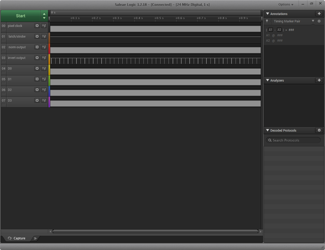
Something very strange is going on in your last logic analyser picture. First there does not appear to be any pulses on the latch/strobe pin. Plus the normal output is changing state, but the inverted output is not changing state until the very last part of the analyser traces. The inverted output should always be the opposite to the normal output.
Mark
Re: My first ZX80.
Posted: Mon Jun 15, 2020 12:46 am
by Muttley Black
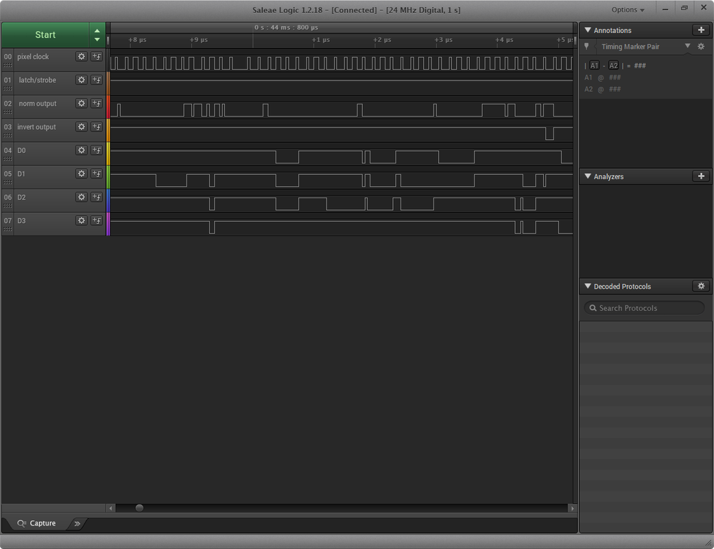
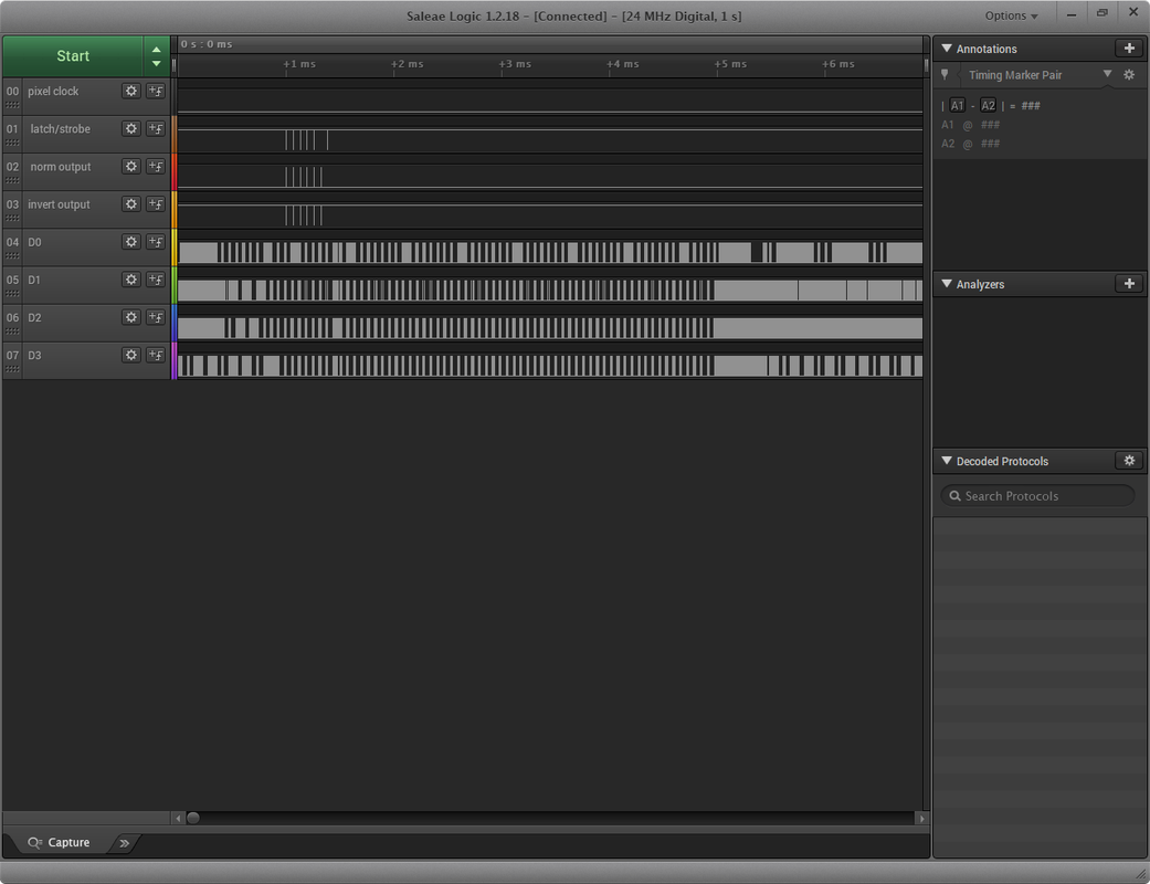
Here are the photos with GND pin connected. There are pulses on the latch/strobe pin now and normal/inverted outputs looks also ok this time. What is missing, is the pixel clock pulses.

Re: My first ZX80.
Posted: Wed Jun 17, 2020 8:26 pm
by Muttley Black
Hello.
Is that normal to have no pulses in IC9 pin2 (pixel clock)?
Thank you
Re: My first ZX80.
Posted: Wed Jun 17, 2020 9:05 pm
by mrtinb
Is the Saleae fast enough to sample in the MHz?
Re: My first ZX80.
Posted: Thu Jun 18, 2020 12:21 am
by 1024MAK
The following is in reference you your last screen.
There must be pulses on the pixel clock input, because there are outputs on both the normal and the inverted outputs shortly after the latch/strobe input sees a pulse.
We don’t know what data bits D4 to D7 are, but based on the output, I suspect at least D5 and D6 were high, and the output stays high reflecting D3 being high. Then the output goes low reflecting D2, D1 and D0 being low.
Based on this, I would say IC9 is working okay
 Mark
Mark