Page 2 of 6
Re: This weekends projects
Posted: Thu Aug 13, 2020 2:49 pm
by mcarlson_sb
Thank you for the readable scans!!!!!
That will make things much easier
Re: This weekends projects
Posted: Thu Aug 13, 2020 3:22 pm
by Moggy
R7 on my board is 4k7 ohm
Re: This weekends projects
Posted: Thu Aug 13, 2020 11:35 pm
by XavSnap
Re: This weekends projects
Posted: Fri Aug 14, 2020 12:32 am
by XavSnap
R7:
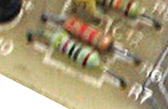
- resistor.jpg (28.72 KiB) Viewed 5296 times
YEL-VIO-BLK-BLK-BRN
470x1 qua:1
470 Ohms 1%
Re: This weekends projects
Posted: Fri Aug 14, 2020 8:56 am
by XavSnap

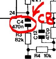
- c8.JPG (18.67 KiB) Viewed 5068 times
Something's wrong in this kind of circuits…
Like "Elletronica mister kit", this article seem to be a rough draft of the original project.
This purpose (article) is clearly sloppy and wrong to sell the greatest number of PCB…
Buy a PCB, and put a bunch of components…
That's all.
Re: This weekends projects
Posted: Fri Aug 14, 2020 1:54 pm
by Moggy
XavSnap wrote: ↑Fri Aug 14, 2020 12:32 am
R7:
resistor.jpg
YEL-VIO-BLK-BLK-BRN
470x1 qua:1
470 Ohms 1%
I have altered my original post here as I've come to the conclusion that on my board, who ever assembled it has reversed R2 and R7 I shall reverse their position and report back as to whether it works or not.
EDIT.
Have now reversed R2-R7 as per the schematic and can report it all works ok.
Re: This weekends projects
Posted: Fri Aug 14, 2020 8:16 pm
by XavSnap
"R" is the decimal notation in the BS1852 format.
https://reviseomatic.org/help/e-resisto ... 0Codes.php
R47 = 0R47 = 0.47 Ohm.
47R = 47R0 = 47 Ohm.
470R= 470R0 = 470 Ohm.
Re: This weekends projects
Posted: Fri Aug 14, 2020 9:52 pm
by Moggy
Er yes I know I'm fully aware how to read resistor code,what does that have to do with R2 and R7 being in the wrong place on my board? I assume this is aimed at me?

I am only pointing out that R7 which should be 470 ohm and R2 which should be 4700 ohm seem to have been swapped on my board regardless of terminology.
Re: This weekends projects
Posted: Fri Aug 14, 2020 11:35 pm
by mcarlson_sb
Maybe it was for me

It was something I didn't know (at least the R47 one - never run across that notation before)
I'm one of the lucky 10000 who learned something today
Re: This weekends projects
Posted: Fri Aug 14, 2020 11:41 pm
by mcarlson_sb
Moggy wrote: ↑Fri Aug 14, 2020 1:54 pm
I have altered my original post here as I've come to the conclusion that on my board, who ever assembled it has reversed R2 and R7 I shall reverse their position and report back as to whether it works or not.
EDIT.
Have now reversed R2-R7 as per the schematic and can report it all works ok.
Thank you.
It's good to know that the design as written (or with the resistors reversed) works.
When I run into issues I now know it's my implementation rather than a design error.