It was working until it stopped

Discussions about Sinclair ZX80 and ZX81 Hardware
User avatar
1024MAK
Posts: 5118
Joined: Mon Sep 26, 2011 10:56 am
Location: Looking forward to summer in Somerset, UK...

Re: It was working until it stopped

Post by 1024MAK »

Dukes909 wrote: Thu Feb 04, 2021 3:47 am All look the same with pulsing but A25 I am not sure by "should be high". It looks high except for a very fast drop; I can attach a screencap if necessary (I didn't have anything to compare these to like the ones in the thread above).
Do you mean pin 25 on the Z80? If yes, this should always be high. It’s connected to the +5V rail via resistor R16.
Dukes909 wrote: Thu Feb 04, 2021 3:47 amOnly other one I wasn't sure about where I was measuring A14 on D7 cathode. They were all pulsing otherwise? I can do screencaps of all if you need me to.
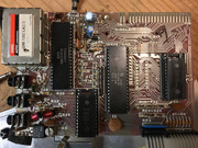
Yes, please do upload pictures. Also take a photo of your board please.

Mark
ZX81 Variations
ZX81 Chip Pin-outs
ZX81 Video Transistor Buffer Amp

:!: Standby alert :!:
There are four lights!
Step up to red alert. Sir, are you absolutely sure? It does mean changing the bulb :!:
Looking forward to summer later in the year.
Dukes909
Posts: 61
Joined: Thu Dec 31, 2020 11:21 am

Re: It was working until it stopped

Post by Dukes909 »

Okay,here we go (you did mean ALL the pics, right? :shock: )

Main board:
1
Image
2
Image
3
Image

Picture of mainboard:

ULA & CPU clocks:
Image

Pin: 16 /INT (should be pulsing)
Image

Pin: 17 /NMI (should be pulsing)
Image

Pin: 18 /HALT (should be pulsing)
Image

Pin: 19 /MREQ (should be pulsing rapidly)
Image

Pin: 21 /RD (should be pulsing rapidly)
Image

Pin: 22 /WR (should be pulsing)
Image

Pin: 24 /WAIT (should be pulsing)
Image

Pin: 25 /BUSRQ (should be high)
Image

Pin: 26 /RESET (should be high, except for a very short time after power is applied)
Image

Pin: 27 /M1 (should be pulsing)
Image

Pin: 28 /RFSH (should be pulsing)
Image

Address lines:
A14
Image

A15
Image

A0
Image

A1
Image

A2
Image

A3
Image

A4
Image

A5
Image

A6
Image

A7
Image

A8
Image

A9
Image

A10
Image

A11
Image

A12
Image

A13
Image

Data lines:
D0
Image

D1
Image

D2
Image

D3
Image

D4
Image

D5
Image

D6
Image

D7
Image

ULA 16
Image

I hope I captured these correctly. Thank you again for your help!
Dukester
Dukes909
Posts: 61
Joined: Thu Dec 31, 2020 11:21 am

Re: It was working until it stopped

Post by Dukes909 »

It doesn't look like the grid from the scope is visible in these. Here is a link to the original images straight from the scope:

https://postimg.cc/gallery/CYBbJPf
User avatar
1024MAK
Posts: 5118
Joined: Mon Sep 26, 2011 10:56 am
Location: Looking forward to summer in Somerset, UK...

Re: It was working until it stopped

Post by 1024MAK »

Okay, the good news is that I think your Z80 is definitely trying to do something. But I think the program has crashed. It may be a RAM problem or a ROM problem. And it’s too early to rule out the Z80 yet. I do think you ULA is okay though.

Because of the (apparently) non-repetitive signals from the address and data pins, the automatic/autoset setting (not the automatic sweep which is completely different) on most ‘scopes gets confused. That’s why I think some of your traces appear distorted or fuzzy. The ‘scope is switching to either an inappropriate timebase (the horizontal range) or an inappropriate voltage range (the vertical range). If possible adjust to using 1V per division or 2V per division. And use a slower timebase so that you get a lot of pulses (if the signal is actually changing) on screen.

The ULA video output pin is showing three levels, which is good. So I think your ULA is probably good.

But no need to do that right now. Let me have a little think.

Mark
ZX81 Variations
ZX81 Chip Pin-outs
ZX81 Video Transistor Buffer Amp

:!: Standby alert :!:
There are four lights!
Step up to red alert. Sir, are you absolutely sure? It does mean changing the bulb :!:
Looking forward to summer later in the year.
User avatar
1024MAK
Posts: 5118
Joined: Mon Sep 26, 2011 10:56 am
Location: Looking forward to summer in Somerset, UK...

Re: It was working until it stopped

Post by 1024MAK »

Do you know if your 16k RAM pack works okay?

If yes, have you tried cleaning the edge connector with IPA (Isopropyl alcohol) and either a eraser designed to remove ink or a PCB scrubber / PCB cleaning block. Go gentle, just the surface dirt needs removing, not the ‘tin plating’. Then test again with your RAM pack.

Next up, is to press firmly down on each and every chip to make sure that they are all properly pushed into their sockets. Try again. If that makes no difference, try removing each chip. Carefully lever them up with a flat bladed screwdriver or blunt knife, working alternating between each end. DO NOT lever against the PCB, instead lever against the plastic of the socket, and gradually and slowly work the chip loose. Also keep a thumb or finger on top. Otherwise if you just apply force from one end, the chip will rotate as it flys out of the socket and you will end up with one or two or more bent or broken pins :cry:

Clean the pins if needed (if they are tarnished, use either a PCB scrubber / PCB cleaning block or a fibreglass cleaning pencil.
Using a magnifying glass and a good light, carefully inspect each socket pin. Compare to the other socket pin contacts. If any appear to be misshapen or there is a large gap between the metal contact and the plastic or metal on the other side of the hole, then you need a new socket.

Do this for all the chips.

Then try again.

If none of the above works, try swapping the Z80 and the ROM between this board and another ZX81 or TS1000. By this, I mean pull the chip from this board, putt the relevant chip from the other board, then put each respective chip in the other board. Then try both boards. Then you can see if the fault/symptoms moved with the chip, or not! You may want to carefully keep notes/track of where each chip started from.

If swapping one chip does not work try the next. But swap the back any previous chips back to where they started. So if you start with the ROM, after swapping, and trying each board, put it back in it’s original machine before you try the Z80.

Mark
ZX81 Variations
ZX81 Chip Pin-outs
ZX81 Video Transistor Buffer Amp

:!: Standby alert :!:
There are four lights!
Step up to red alert. Sir, are you absolutely sure? It does mean changing the bulb :!:
Looking forward to summer later in the year.
Dukes909
Posts: 61
Joined: Thu Dec 31, 2020 11:21 am

Re: It was working until it stopped

Post by Dukes909 »

1024MAK wrote: Tue Feb 09, 2021 12:18 am Because of the (apparently) non-repetitive signals from the address and data pins, the automatic/autoset setting (not the automatic sweep which is completely different) on most ‘scopes gets confused. That’s why I think some of your traces appear distorted or fuzzy. The ‘scope is switching to either an inappropriate timebase (the horizontal range) or an inappropriate voltage range (the vertical range). If possible adjust to using 1V per division or 2V per division. And use a slower timebase so that you get a lot of pulses (if the signal is actually changing) on screen.

Mark
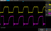
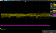
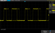
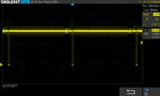
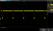
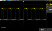
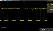
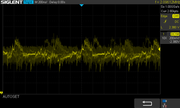
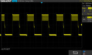
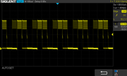
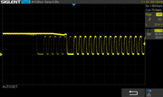
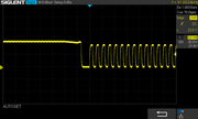
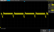
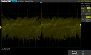
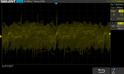
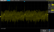
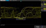
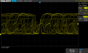
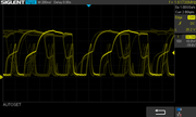
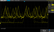
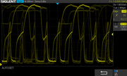
Thank you for looking at these. I can change the vertical voltage to 1V or 2V per division with a slower timebase. Do you want me to repeat with just the address and data pins?
User avatar
1024MAK
Posts: 5118
Joined: Mon Sep 26, 2011 10:56 am
Location: Looking forward to summer in Somerset, UK...

Re: It was working until it stopped

Post by 1024MAK »

No, not yet. Try my other suggestions first.

Mark
ZX81 Variations
ZX81 Chip Pin-outs
ZX81 Video Transistor Buffer Amp

:!: Standby alert :!:
There are four lights!
Step up to red alert. Sir, are you absolutely sure? It does mean changing the bulb :!:
Looking forward to summer later in the year.
Dukes909
Posts: 61
Joined: Thu Dec 31, 2020 11:21 am

Re: It was working until it stopped

Post by Dukes909 »

1024MAK wrote: Tue Feb 09, 2021 12:39 am Do you know if your 16k RAM pack works okay?
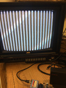
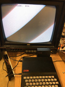
Yes, it does, or at least it worked the very first day I received this and I used some code from this board to display the following and posted my Hoorays on the Welcome board, and then the dreaded wonky screen happened and I haven't been able to get "K" cursor since. :roll:
Image
1024MAK wrote: Tue Feb 09, 2021 12:39 am If yes, have you tried cleaning the edge connector with IPA (Isopropyl alcohol) and either a eraser designed to remove ink or a PCB scrubber / PCB cleaning block. Go gentle, just the surface dirt needs removing, not the ‘tin plating’. Then test again with your RAM pack.
Ok, I don't have PCB scrubber (I will to look up what that is) but I do have IPA to use on there (I might have an IPA myself now that you mention it) I will try this tonight.
1024MAK wrote: Tue Feb 09, 2021 12:39 am Clean the pins if needed (if they are tarnished, use either a PCB scrubber / PCB cleaning block or a fibreglass cleaning pencil.
Using a magnifying glass and a good light, carefully inspect each socket pin. Compare to the other socket pin contacts. If any appear to be misshapen or there is a large gap between the metal contact and the plastic or metal on the other side of the hole, then you need a new socket.

Do this for all the chips. Then try again.
Ok sounds like I need to do some shopping for PCB scrubber or fibreglass pencil.
1024MAK wrote: Tue Feb 09, 2021 12:39 am If none of the above works, try swapping the Z80 and the ROM between this board and another ZX81 or TS1000. By this, I mean pull the chip from this
This may take a while as I don't have another working machine but am watching some on the interweb as you probably gathered from my other post about asking whether TS1000 parts are compatible.

Will report back... A VERY BIG THANK YOU :D

Dukester
Dukes909
Posts: 61
Joined: Thu Dec 31, 2020 11:21 am

Re: It was working until it stopped

Post by Dukes909 »

Well, I don't know if it is progress or not, but after cleaning the contacts on the motherboard, then removing and cleaning each pin on each chip and reinstalling, I now get a screen of solid black & white bars rather than the solid white.
Image
I guess I will be looking for another (hopefully working) machine to swap components with.

Dukester
Post Reply