
I am in the process of restoring a zx81. I actually thought I had completed it!
I changed the RF for the composite pcb from zx renew which worked brilliantly. I then changed the keyboard as the ribbon was a bit damaged on the original. Everything was working perfectly until suddenly the screen changed to having dark vertical bands down it and when you type anything it generates a wierd triangular shape below the text, I've tried to capture it in the photo. The vertical bands are difficult to see in the picture.
I can't really pin point what I did when the screen changed. It's possible that my son accidently pulled the power jack out of the side of the computer. Can't imagine this would cause this though.
Any help greatfully received!
Paul

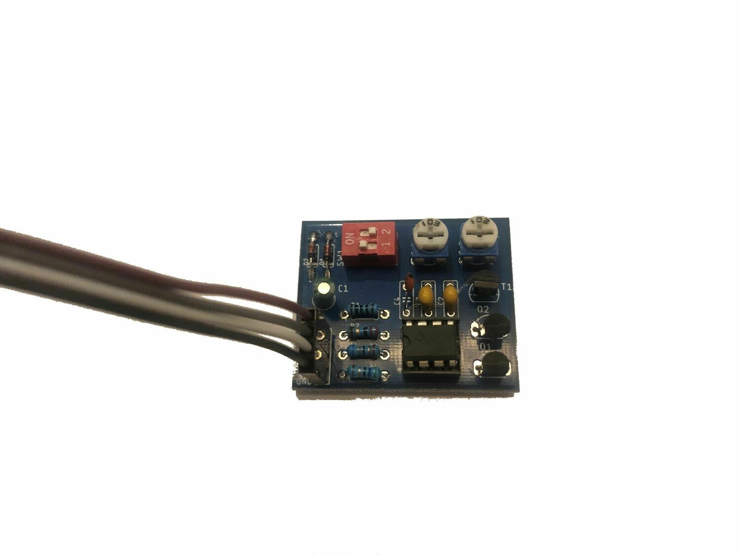 or this one
 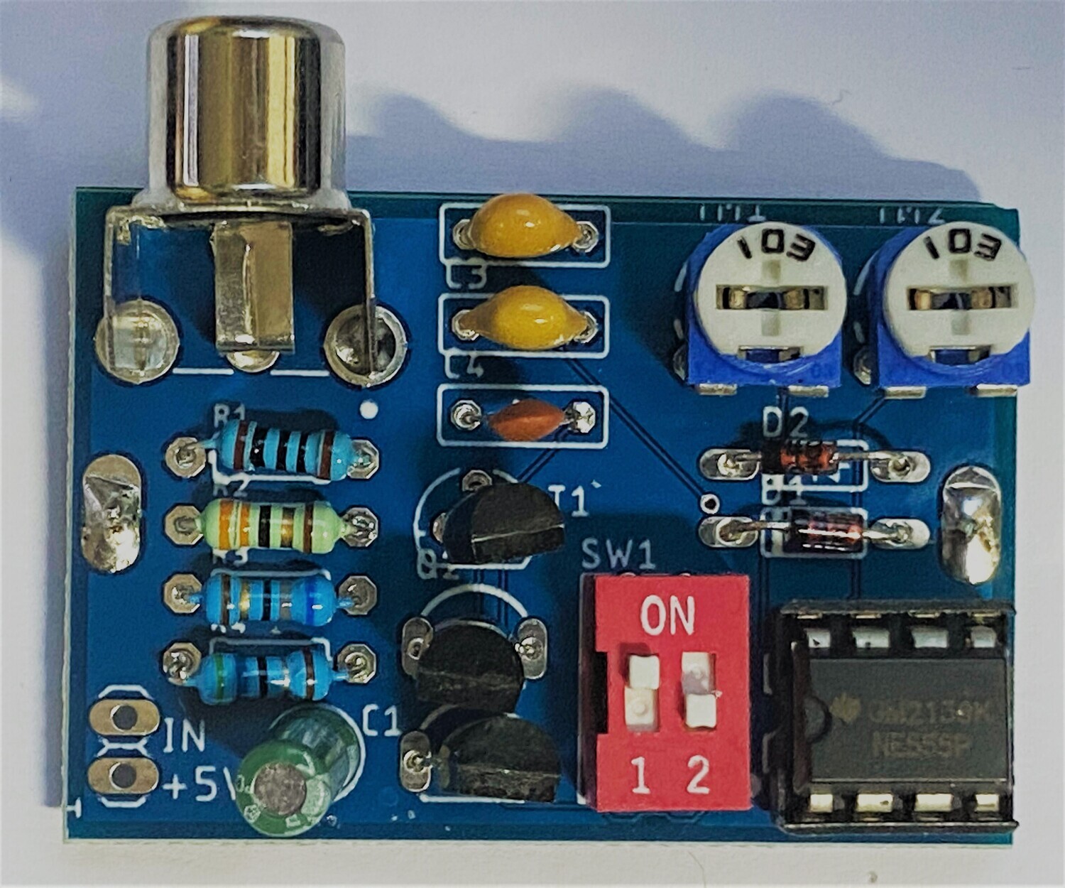 or a different one?