
I'm planning to do a composite mod on my Timex Sinclair 1000 by using a "TS1000 and ZX81 Composite Video Adaptor Kit" I purchased via ETSY. I'm waiting for it to be delivered. In the meantime, I have been viewing some composite mod videos on YouTube. One that I found particularly interesting is this one https://www.youtube.com/watch?v=7SFuLd1Tjy4 titled "How to add composite out to a Sinclair ZX81". I like this video because the person in the video connects the new composite mod board to the existing connections in the Sinclair, thus preserving the RF video output while also adding the ability to use composite by merely changing what type of monitor/TV is connected. This is something that I would like to do as well.
My Sinclair unit has a modulator that has three solid wires coming out through the three exit holes. Those wires (ground, power, and video) are soldered directly onto connections on the board just below each corresponding exit hole. There are no components between the ULA chip and the modulator, so I'm thankful for that. For reference, My ULA is a 2C184E.
In the video I provided a link to, the user connects his mod board (same kind I ordered) to the unit in a variety of ways. One being directly onto the back of the motherboard, and another to the modulator and other parts of the system. He finally solders all of the connections and places the mod board on the exterior top of the modulator housing via double sided tape.
So here's my question: After I solder 5 wires to the mod board (2 ground, 2 video, and 1 power), can I use wires with alligator clips as temporary jumpers to connect the wires from the mod board to the existing three solid wires (ground, power, video), the existing RCA connector (video), and the remaining ground to the modulator chassis to test the mod board while not disconnecting any existing RF connections? It's just a thought right now, because the clips might end up being too close to each other and might touch (which I don't want to happen).
I'm practicing my soldering before I attempt anything. I won't move forward until I feel very confident in my soldering skills.
Joe
NEWBIE - Composite Mod planned, and related question
-
1024MAK

- Posts: 5118
- Joined: Mon Sep 26, 2011 10:56 am
- Location: Looking forward to summer in Somerset, UK...
Re: NEWBIE - Composite Mod planned, and related question
For the benefit of others reading this, the video board that is being discussed is a ZX8-CCB.
To attach the black/0V/GND/ground to the modulator, you can either try to get it to hold on to the “fingers” of the lid of the modulator. Or pop the lid off and then clip to the case of the modulator. Or cheat and clip to the metal heatsink of the 7805 voltage regulator, or to one of the “earthing”/‘grounding” spring metal that press against the case.
I’ll post some photos later…
Mark
Small correction here. A TS1000 has a modulator that can output on one of two different frequencies (or TV channels). The switch is mounted on the main board. Hence the three wires going into the VHF modulator are switch input (can be 0V/GND/ground or +5V/power to select the different frequencies), +5V/power and the video input signal. The connection to 0V/GND/ground is via the solder connections that hold the modulator to the board.
Taking into account my comments above, yes, you can use alligator clips (we call them croc clips, short for crocodile). I do recommend small ones though. I myself use miniature probes that hook on to wires or component wires.USAJoe wrote: ↑Wed Apr 12, 2023 6:10 am In the video I provided a link to, the user connects his mod board (same kind I ordered) to the unit in a variety of ways. One being directly onto the back of the motherboard, and another to the modulator and other parts of the system. He finally solders all of the connections and places the mod board on the exterior top of the modulator housing via double sided tape.
So here's my question: After I solder 5 wires to the mod board (2 ground, 2 video, and 1 power), can I use wires with alligator clips as temporary jumpers to connect the wires from the mod board to the existing three solid wires (ground, power, video), the existing RCA connector (video), and the remaining ground to the modulator chassis to test the mod board while not disconnecting any existing RF connections? It's just a thought right now, because the clips might end up being too close to each other and might touch (which I don't want to happen).
To attach the black/0V/GND/ground to the modulator, you can either try to get it to hold on to the “fingers” of the lid of the modulator. Or pop the lid off and then clip to the case of the modulator. Or cheat and clip to the metal heatsink of the 7805 voltage regulator, or to one of the “earthing”/‘grounding” spring metal that press against the case.
I’ll post some photos later…
Mark
ZX81 Variations
ZX81 Chip Pin-outs
ZX81 Video Transistor Buffer Amp
 Standby alert
There are four lights!
Step up to red alert. Sir, are you absolutely sure? It does mean changing the bulb
Looking forward to summer later in the year.
ZX81 Chip Pin-outs
ZX81 Video Transistor Buffer Amp
There are four lights!
Step up to red alert. Sir, are you absolutely sure? It does mean changing the bulb
Looking forward to summer later in the year.
-
Lardo Boffin
- Posts: 2173
- Joined: Sat Nov 26, 2016 2:42 am
Re: NEWBIE - Composite Mod planned, and related question
Interesting video thanks Joe!
I didn’t know it was possible to have both RF and composite video from the same socket using a ZX8-CCB.
Does anyone know if doing this is likely to cause any issues?
I didn’t know it was possible to have both RF and composite video from the same socket using a ZX8-CCB.
Does anyone know if doing this is likely to cause any issues?
ZX80
ZX81 iss 1 (bugged ROM, kludge fix, normal, rebuilt)
TS 1000 iss 3, ZXPand AY and +, ZX8-CCB, ZX-KDLX & ChromaSCART
Tatung 81 + Wespi
TS 1500 & 2000
Spectrum 16k (iss 1 s/n 862)
Spectrum 48ks plus a DIVMMC future and SPECTRA
ZX81 iss 1 (bugged ROM, kludge fix, normal, rebuilt)
TS 1000 iss 3, ZXPand AY and +, ZX8-CCB, ZX-KDLX & ChromaSCART
Tatung 81 + Wespi
TS 1500 & 2000
Spectrum 16k (iss 1 s/n 862)
Spectrum 48ks plus a DIVMMC future and SPECTRA
Re: NEWBIE - Composite Mod planned, and related question
It is recommended to desolder the resistor at the RF OUT and reconnect it via a 33pF ceramic capacitor for decoupleing purpose.Lardo Boffin wrote: ↑Wed Apr 12, 2023 10:35 am
Does anyone know if doing this is likely to cause any issues?
This way both RF and video will be fine.
In theory, there is no difference between theory and practice. But, in practice, there is.
-
Lardo Boffin
- Posts: 2173
- Joined: Sat Nov 26, 2016 2:42 am
Re: NEWBIE - Composite Mod planned, and related question
Thanks Paul.Paul wrote: ↑Wed Apr 12, 2023 11:10 amIt is recommended to desolder the resistor at the RF OUT and reconnect it via a 33pF ceramic capacitor for decoupleing purpose.Lardo Boffin wrote: ↑Wed Apr 12, 2023 10:35 am
Does anyone know if doing this is likely to cause any issues?
This way both RF and video will be fine.
I assume you mean this resistor?
ZX80
ZX81 iss 1 (bugged ROM, kludge fix, normal, rebuilt)
TS 1000 iss 3, ZXPand AY and +, ZX8-CCB, ZX-KDLX & ChromaSCART
Tatung 81 + Wespi
TS 1500 & 2000
Spectrum 16k (iss 1 s/n 862)
Spectrum 48ks plus a DIVMMC future and SPECTRA
ZX81 iss 1 (bugged ROM, kludge fix, normal, rebuilt)
TS 1000 iss 3, ZXPand AY and +, ZX8-CCB, ZX-KDLX & ChromaSCART
Tatung 81 + Wespi
TS 1500 & 2000
Spectrum 16k (iss 1 s/n 862)
Spectrum 48ks plus a DIVMMC future and SPECTRA
-
1024MAK
- Posts: 5118
- Joined: Mon Sep 26, 2011 10:56 am
- Location: Looking forward to summer in Somerset, UK...
Re: NEWBIE - Composite Mod planned, and related question
That’s the one, yes.
Mark
ZX81 Variations
ZX81 Chip Pin-outs
ZX81 Video Transistor Buffer Amp
Standby alert
There are four lights!
Step up to red alert. Sir, are you absolutely sure? It does mean changing the bulb
Looking forward to summer later in the year.
ZX81 Chip Pin-outs
ZX81 Video Transistor Buffer Amp
There are four lights!
Step up to red alert. Sir, are you absolutely sure? It does mean changing the bulb
Looking forward to summer later in the year.
-
1024MAK
- Posts: 5118
- Joined: Mon Sep 26, 2011 10:56 am
- Location: Looking forward to summer in Somerset, UK...
Re: NEWBIE - Composite Mod planned, and related question
Here’s an old photo showing my “test” ZX8-CCB connected to a ZX80:
(From this post)
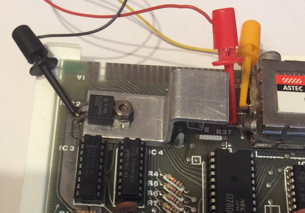
ZX8-CCB connection points for a TS1000 or USA ZX81:
(Click the photo for a bigger image)
In a TS1000 or USA ZX81, the video output from the ULA does not directly go to the modulator video input. Instead it passes through diode D9 and a resistor. Hence it’s better to pick the signal up at one end of diode D9 as shown.
Mark
(From this post)
ZX8-CCB connection points for a TS1000 or USA ZX81:
- ZX8-CCB connection points for a TS1000 or USA ZX81
In a TS1000 or USA ZX81, the video output from the ULA does not directly go to the modulator video input. Instead it passes through diode D9 and a resistor. Hence it’s better to pick the signal up at one end of diode D9 as shown.
Mark
ZX81 Variations
ZX81 Chip Pin-outs
ZX81 Video Transistor Buffer Amp
Standby alert
There are four lights!
Step up to red alert. Sir, are you absolutely sure? It does mean changing the bulb
Looking forward to summer later in the year.
ZX81 Chip Pin-outs
ZX81 Video Transistor Buffer Amp
There are four lights!
Step up to red alert. Sir, are you absolutely sure? It does mean changing the bulb
Looking forward to summer later in the year.
-
Lardo Boffin
- Posts: 2173
- Joined: Sat Nov 26, 2016 2:42 am
Re: NEWBIE - Composite Mod planned, and related question
ZX80
ZX81 iss 1 (bugged ROM, kludge fix, normal, rebuilt)
TS 1000 iss 3, ZXPand AY and +, ZX8-CCB, ZX-KDLX & ChromaSCART
Tatung 81 + Wespi
TS 1500 & 2000
Spectrum 16k (iss 1 s/n 862)
Spectrum 48ks plus a DIVMMC future and SPECTRA
ZX81 iss 1 (bugged ROM, kludge fix, normal, rebuilt)
TS 1000 iss 3, ZXPand AY and +, ZX8-CCB, ZX-KDLX & ChromaSCART
Tatung 81 + Wespi
TS 1500 & 2000
Spectrum 16k (iss 1 s/n 862)
Spectrum 48ks plus a DIVMMC future and SPECTRA
Re: NEWBIE - Composite Mod planned, and related question
Thanks to all that replied! I really appreciate it.
Here are some photos of my 1000. As you can see it's different from the photos posted here. You can see that there's no components between the modulator and the ULA chip. The RCA connector is also at the opposite end, and the modulator components look a little different (at least to me).
Joe
Here are some photos of my 1000. As you can see it's different from the photos posted here. You can see that there's no components between the modulator and the ULA chip. The RCA connector is also at the opposite end, and the modulator components look a little different (at least to me).
-
1024MAK
- Posts: 5118
- Joined: Mon Sep 26, 2011 10:56 am
- Location: Looking forward to summer in Somerset, UK...
Re: NEWBIE - Composite Mod planned, and related question
The photo of the modulator connections is that of a Sinclair ZX81 issue 3 board, as used in both U.K./European ZX81 computers and some Timex TS1000 computers.
There are also ZX81 issue one boards, used in U.K./European ZX81 computers. It’s possible that some may have made it to America in Sinclair ZX81 machines.
No one (that we know of) has ever seen an issue two board.
And there are Sinclair/Timex TS1000 issue boards marked “Sinclair ZX81 USA Issue One” which are noticeably different to the boards used in the U.K./European ZX81 computers. Here is an image of of one of these:
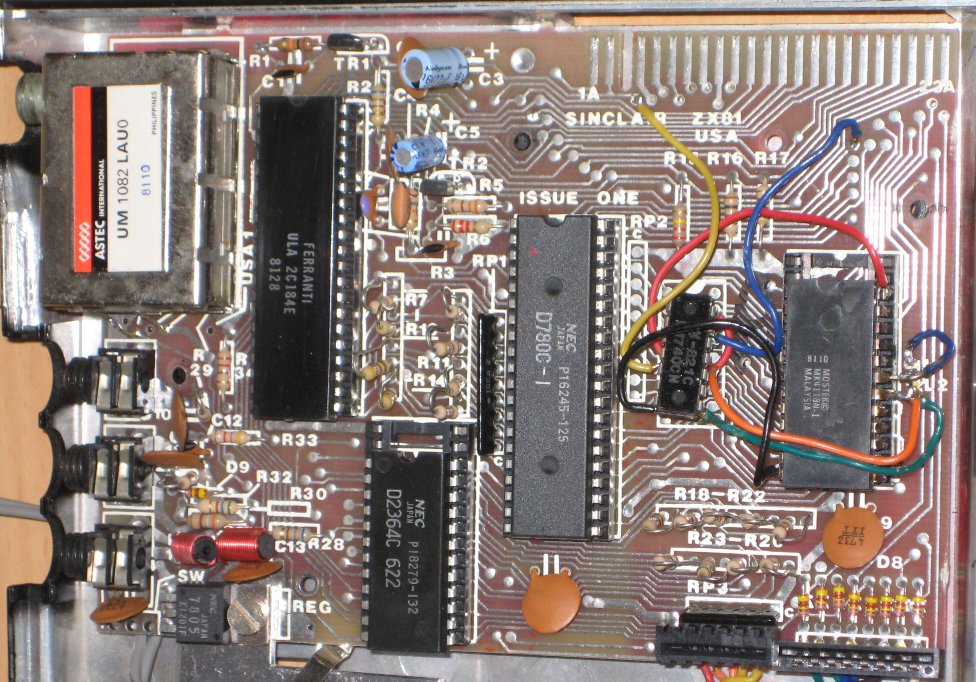
Is this board like yours (ignore the modifications that have been made since it was originally manufactured).
Mark
There are also ZX81 issue one boards, used in U.K./European ZX81 computers. It’s possible that some may have made it to America in Sinclair ZX81 machines.
No one (that we know of) has ever seen an issue two board.
And there are Sinclair/Timex TS1000 issue boards marked “Sinclair ZX81 USA Issue One” which are noticeably different to the boards used in the U.K./European ZX81 computers. Here is an image of of one of these:
Is this board like yours (ignore the modifications that have been made since it was originally manufactured).
Mark
ZX81 Variations
ZX81 Chip Pin-outs
ZX81 Video Transistor Buffer Amp
Standby alert
There are four lights!
Step up to red alert. Sir, are you absolutely sure? It does mean changing the bulb
Looking forward to summer later in the year.
ZX81 Chip Pin-outs
ZX81 Video Transistor Buffer Amp
There are four lights!
Step up to red alert. Sir, are you absolutely sure? It does mean changing the bulb
Looking forward to summer later in the year.