
Alright, so the video out device arrived, which is cool.
Now, I've got to figure out how to install it on my TS 1500.
It does come with instructions, but they're for a ZX81, and I'll surely find a way to screw it up, seeing as how I've still never successfully modified anything electronic.
PS: Does the device negate a need for the RF adapter ... i.e. once it's installed, can you plug the machine directly into the video-in port on your friendly TV?
Times Sinclair 1500 video out
Re: Times Sinclair 1500 video out
Hi, the best way on the ZX81 is to locate the two wires going into the RF modulator. One is 5V the other is signal. If you are keeping the RF Modulator or testing connect the input red (5V)/yellow(signal) to these and the black to a suitable earth. The other two wires go to a composite socket.jegs2 wrote:Alright, so the video out device arrived, which is cool.
Now, I've got to figure out how to install it on my TS 1500.
It does come with instructions, but they're for a ZX81, and I'll surely find a way to screw it up, seeing as how I've still never successfully modified anything electronic.
PS: Does the device negate a need for the RF adapter ... i.e. once it's installed, can you plug the machine directly into the video-in port on your friendly TV?
If you are replacing the RF modulator, desolder it and remove the innards. Reattach the casing to the board, insulate the bottom with a piece of card or something and sit the new unit inside. Bring the 5V and signal wires through the side and solder to the ZX81 board where the original inputs came from. Use the inner wall of the case as earth and the orange composite wire to the centre pin of the TV socket.
Tune it in , pop the lid back on and you wouldn't know it was there.
Re: Times Sinclair 1500 video out
Thanks, those are great detailed instructions for the ZX-81, and the instructions shipped with the device include a picture of where to put wires, for folks like me.
Unfortunately, my unit is a TS-1500, so the instructions are minimally useful.
Unfortunately, my unit is a TS-1500, so the instructions are minimally useful.
Re: Times Sinclair 1500 video out
A schematic can be found here in the download section....
http://www.zx81.de/webring/index.htm
Not the best quality but should be useful.
http://www.zx81.de/webring/index.htm
Not the best quality but should be useful.

Re: Times Sinclair 1500 video out
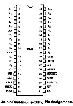
Actually I am not very familiar with the TS1500 - but you can get +5V (red) from Pin 11 of Z80 CPU and GND (black) from Pin 29 of Z80.
Can see picture of IC here:
http://www.z80.eu/z80pin.jpg
Please check number one pin and if soldering from solder side check for eventually mirrored pin out.
The yellow cable (video in) can be connected directly to the modulator in, the middle pin.
The output orange and black can be soldered to a video/RCA jack (chinch) whil black is GND (outer signal) and orange inner signal.
Re: Times Sinclair 1500 video out
Thanks. I'll try that out.
Re: Times Sinclair 1500 video out
Okay, so got the job mostly done (soldering-wise anyway), except for the following, which confused me:
Not sure where to find that. Here are some pics of what I've done. If you can point out where I'm supposed finish, I'd be grateful.PokeMon wrote:The output orange and black can be soldered to a video/RCA jack (chinch) whil black is GND (outer signal) and orange inner signal.
- Attachments
-
- Closeup of video-in wire (TS 1500).JPG (167.58 KiB) Viewed 5155 times
-
- Closeup of Z80 Soldering Job (TS 1500).JPG (203.84 KiB) Viewed 5155 times
-
- TS 1500 Main Board with Mod (incomplete).JPG
- (631.88 KiB) Downloaded 393 times
-
1024MAK

- Posts: 5118
- Joined: Mon Sep 26, 2011 10:56 am
- Location: Looking forward to summer in Somerset, UK...
Re: Times Sinclair 1500 video out
The input to the new ZX8-CCB video circuit (the yellow wire) needs to be connected to the video output of the "ULA" chip. On the TS1500, the "ULA" is the square surface mounted chip.
One place to pick up this signal is on the anode leg of diode D19. You want the solder side of the board, and the diode connection nearest the crystal (the crystal is in the metal silver can that has two connection leads next to the diode, the identity on the PCB for the crystal is "X1").
The output (orange wire) from the new ZX8-CCB video circuit needs to go to a RCA / phono / chinch connector (known by different names in different parts of the world).
The orange coloured wire is the video signal and either one of the black wires connects to the 0V/ground/shield.
Connect the orange coloured wire to the inner pin and connect the black wire to the outer / sleeve connection.
For testing, for now, I would buy an in line cable socket and use that. Later once you have it working, you can decide if you want to have a composite video output socket (and keep the RF output), or if you want to disconnect the RF output and wire the composite output in it's place.
If you follow my instructions above, and do not make any connections to the modulator or it's output socket. Then the modulator and it's RF output should still work (remove any connections that you have already made to the modulator and restore it to how it was originally).
Note that as the new ZX8-CCB video circuit has been set for for a ZX81, both variable resistors (presets) will need to be carefully set up.
I hope this helps.
Mark
ZX81 Variations
ZX81 Chip Pin-outs
ZX81 Video Transistor Buffer Amp
 Standby alert
There are four lights!
Step up to red alert. Sir, are you absolutely sure? It does mean changing the bulb
Looking forward to summer later in the year.
ZX81 Chip Pin-outs
ZX81 Video Transistor Buffer Amp
There are four lights!
Step up to red alert. Sir, are you absolutely sure? It does mean changing the bulb
Looking forward to summer later in the year.
Re: Times Sinclair 1500 video out
I put it together as recommended, and from that output I get only a dark screen.
To see if my computer was still functional, I did hook up the video to the TV-out, and got the usual crappy picture with full functionality.
So, don't know where I went wrong. Pics are forthcoming.
To see if my computer was still functional, I did hook up the video to the TV-out, and got the usual crappy picture with full functionality.
So, don't know where I went wrong. Pics are forthcoming.
- Attachments
-
- TS 1500 Video Mod Yellow Wire Closeup.JPG (77.82 KiB) Viewed 5125 times
-
- TS 1500 Video Mod Black and Red Wires Closeup.JPG (94.91 KiB) Viewed 5125 times
-
- TS 1500 Pin Side with Video Mod.JPG
- (527.44 KiB) Downloaded 363 times
Re: Times Sinclair 1500 video out
As for the RCA Jack, connected the black wire to the outside (jacket) wire, and the orange one to the center wire.
- Attachments
-
- TS 1500 Video Mod RCA Jack.JPG
- (344.89 KiB) Downloaded 363 times